

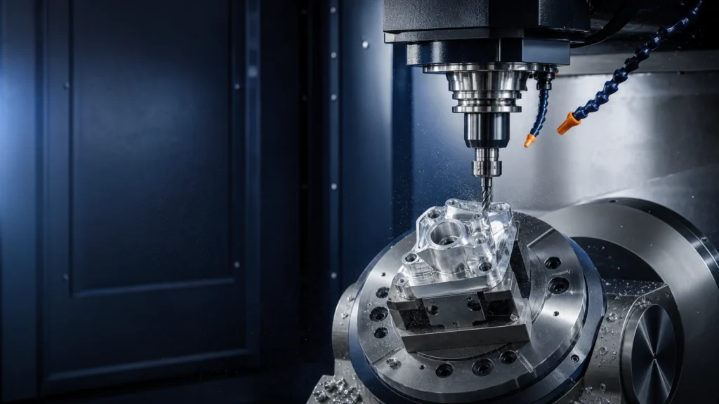
Manufacturing knowledge center
CNC Machining: A Practical Guide from CAD File to Precision Part
Good parts are rarely the result of simply pressing “run.” They come from clear design intent, sensible tolerances, the right material, and a machining plan that respects how a cutter actually reaches a feature.
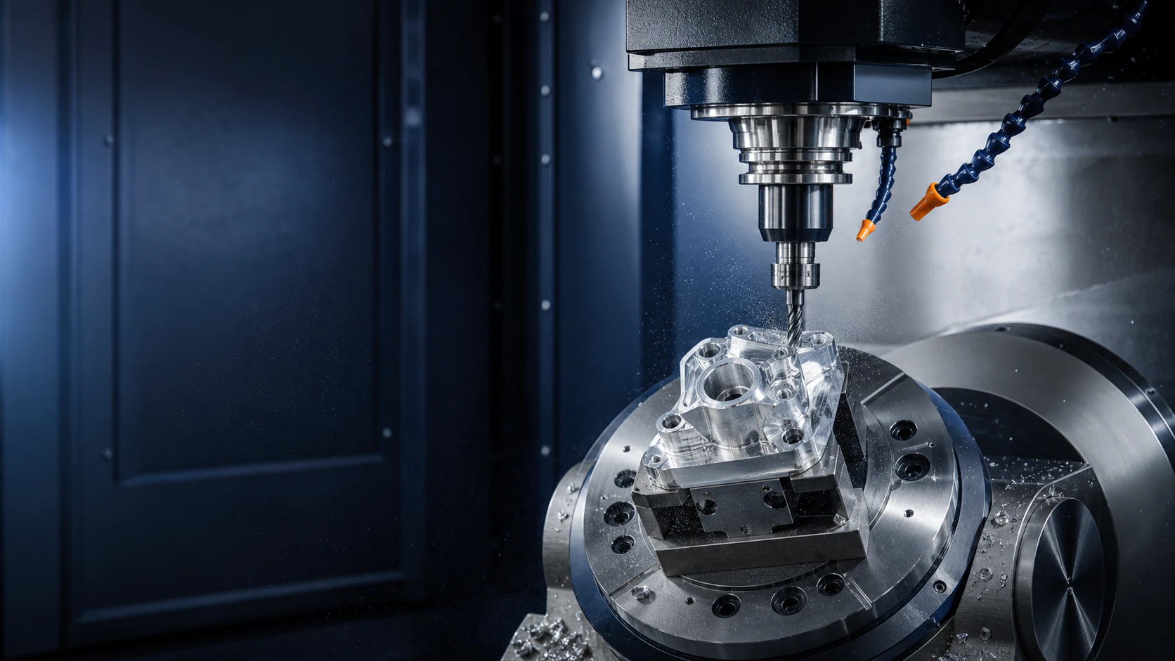
There is a familiar moment in product development: a team has a clean CAD model, a tight deadline, and a part that looks straightforward on screen. Then the manufacturing questions arrive. Can the internal corner be cut? Does that tolerance really need to be so tight? Will the thin wall move when it is released from the fixture? CNC machining is often selected because it answers these questions with a robust, repeatable process—not because it makes the questions disappear.
For prototypes, bridge production, fixtures, and end-use components, CNC machining remains a flexible route from a digital model to a physical part. It works with metals and engineering plastics, supports fine detail, and accommodates design revisions without dedicated tooling. This guide covers the choices that make a precision CNC machining project easier to quote, inspect, and get right first time.
What CNC machining really does
CNC stands for computer numerical control. A programmer translates CAD geometry and manufacturing intent into controlled tool movements. A cutter removes material in milling; a clamped workpiece rotates against a cutting tool in turning. Modern machines can combine multiple axes, probing, and automated work holding, but the core principle is unchanged: material is removed until the remaining shape matches the drawing.
The important word is “matches.” A model may define nominal dimensions, while a manufactured part must also meet functional requirements: fit with a mating part, thread engagement, sealing, stiffness, surface condition, and cosmetic expectations. A capable CNC machining service therefore starts by reading the drawing as an engineering document rather than treating it as a list of numbers.
Choosing CNC milling, CNC turning, or a combined process
Process selection is driven by geometry. CNC milling is the natural choice for prismatic forms: housings, brackets, plates, pockets, ribs, contours, and drilled patterns. It is especially useful when several faces need to be machined at different orientations. Three-axis milling covers a great deal of work; fourth- and five-axis strategies reduce re-clamping and make angled features more accessible.
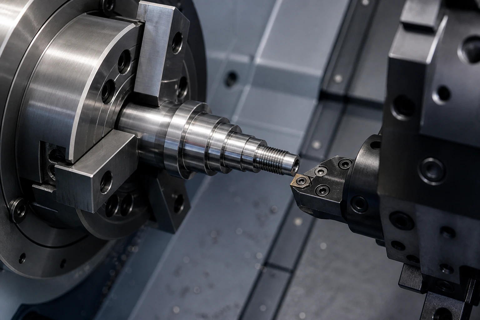
CNC turning is typically the efficient route for rotational parts such as shafts, bushings, pins, threaded bodies, and nozzles. It produces concentric diameters efficiently because the datum is established around the part axis. When a turned component also needs flats, cross holes, slots, or small milled details, turn-mill equipment can complete more of the work in one setup.
Turning, facing, and milling at a glance
The easiest way to distinguish these operations is to watch what rotates and how the cutting tool travels. In turning, the workpiece rotates while a single-point tool normally feeds parallel to its axis to reduce diameter. Facing also rotates the workpiece, but the tool feeds across the end to establish a flat face or control length. During milling, the multi-edge cutter rotates while the workpiece is held in a fixture.
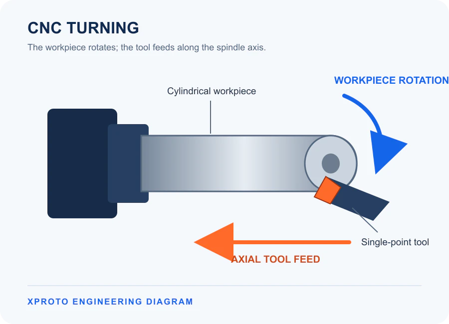
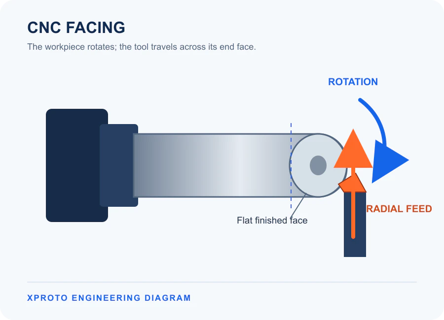
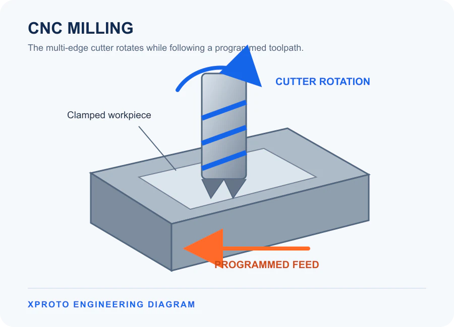
Original engineering diagrams created for Xproto. The layouts, colors, labels, and illustrations may be reused on Xproto-owned pages.
| Part characteristic | Usually a good starting process | Question to ask |
|---|---|---|
| Mostly flat faces, pockets, and hole patterns | CNC milling | Can tools reach every pocket and internal corner? |
| Diameters, grooves, threads, and axial holes | CNC turning | Which diameter should control concentricity? |
| Slender, detail-rich cylindrical parts | Turn-mill or Swiss-type machining | Would fewer setups protect the datum chain? |
| Multiple angled faces or compound curves | Multi-axis CNC machining | Can work holding be simplified? |
Do not choose a process solely because it is familiar. A part that can be milled may still be more stable and economical when turned first. Conversely, adding a small flat to a shaft does not automatically require a second supplier. Early feedback on the machining sequence is where custom CNC machining becomes a design advantage rather than a purchasing line item.
Design choices that affect cost, lead time, and quality
Most avoidable cost in CNC machining is designed into the part before a tool touches material. The goal is not to make a design generic; it is to make the critical details intentional. Start with tolerances. A blanket tolerance that is tighter than the function demands can slow programming, require extra finishing passes, and expand inspection. Apply close tolerances to the features that control fit, motion, sealing, or alignment. Let non-critical dimensions use a sensible general tolerance.
Internal corners deserve the same attention. Standard rotating tools create radii, so a perfectly square internal corner needs a secondary method or a design change. Calling out a practical corner radius often makes a pocket faster to mill and less likely to leave an unsupported thin tool at the bottom. Deep, narrow pockets should be considered carefully as well: tool reach, chip evacuation, and vibration all become more difficult as depth increases relative to width.
Four DFM checks worth making before requesting a quote
- Tool access: Every machined face needs a realistic path for a tool and, later, for measurement.
- Wall thickness: Thin walls can deflect under cutting force or distort after material removal. Keep them as substantial as the function allows.
- Thread details: State thread standard, class, depth, and whether the thread is through or blind. Leave clearance at blind-hole bottoms.
- Datums: Identify the features that matter relative to one another. This helps the machinist choose setup surfaces and helps inspection focus on what is functional.
A clear drawing still matters, even with a complete 3D model. The model communicates geometry; the drawing should communicate requirements that geometry cannot always express: material condition, finish, deburr expectations, inspection dimensions, and revision control. For a complex assembly, it is also helpful to identify mating components or explain the operating environment. That one sentence of context can prevent the wrong trade-off.
Material and finishing decisions
Material selection is a conversation between function and manufacturability. Aluminum suits lightweight structures and prototype parts. Stainless steel adds corrosion resistance and strength; alloy steel may be selected for hardness or fatigue performance. Brass is useful for fittings and electrical components, while engineering plastics can reduce weight or insulate electrically.
Each material changes the machining strategy. Aluminum can cut quickly but show handling marks; stainless retains heat and requires attention to tool wear; plastics need controlled clamping to avoid deformation. A specific material callout—not merely “aluminum” or “steel”—improves a CNC machining quote. Grade, temper, and condition matter.
Finish is another functional choice. As-machined surfaces can be perfectly appropriate for internal faces or prototype work. Bead blasting may create a uniform matte appearance; anodizing can improve aluminum’s surface protection and provide color; passivation supports corrosion resistance for suitable stainless parts. If a sealing face, bearing fit, or cosmetic surface is critical, mark it clearly. The supplier can then protect it during fixturing, finishing, and packing.
A practical quality-control workflow
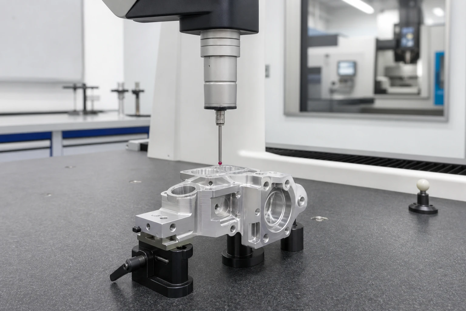
Quality is most reliable when planned alongside the machining method. The model, drawing, and material are reviewed first; during first-off production, key dimensions are verified before the full quantity is made. Depending on the part, tools may include micrometers, pin and thread gauges, optical measurement, or a coordinate measuring machine (CMM).
For precision CNC machining, separate critical-to-function features from routine dimensions. Critical features may need a first-article report and in-process checks. This makes inspection proportionate and prompts a better question than “Can you hold tolerance?”: “How will you establish and verify this datum relationship?”
Communication closes the loop. If an edge needs a specific break, if a burr is unacceptable because it sits near an optical path, or if a component is paired in an assembly, say so when the order is placed. The best CNC machining outcomes usually come from a short technical exchange before production, not from discovering an assumption after delivery.
From upload to a part you can trust
Good CNC machining is a collaboration between design, programming, setup, cutting, and inspection. The CAD file begins the process, but datum choices, functional tolerances, tool access, and inspection planning shape the final result. Make those decisions early and the process becomes faster, more predictable, and easier to repeat.
For a new RFQ, send the 3D model, a drawing for critical requirements, quantity, material, finish, and known functional risks. That gives a manufacturing team enough context to start a useful DFM conversation.
Q&A: CNC Machining
What file formats are best for CNC machining?
STEP files are widely useful because they preserve solid geometry cleanly. IGES, Parasolid, and native CAD formats may also be accepted. Include a PDF drawing when tolerances, threads, finishes, or inspection requirements are important.
How tight should CNC machining tolerances be?
Use the tolerance required by the function. Critical locating, sealing, and bearing features may require close control; non-critical features should use a practical general tolerance. Tightening every dimension can add cost without improving the part.
When should I choose CNC milling instead of CNC turning?
Choose milling for parts dominated by flat faces, pockets, contours, and hole patterns. Choose turning for parts dominated by concentric diameters and axial geometry. A combined turn-mill process can suit parts that need both.
Is CNC machining suitable for both prototypes and production parts?
Yes. It is particularly valuable for prototypes, low- and medium-volume orders, custom fixtures, and production components where material performance and precise geometry are important.
What should I include in a CNC machining RFQ?
Provide the 3D model, PDF drawing, quantity, material grade, finish, target date, and any features that are critical to fit or performance. Identifying the assembly function is also helpful.
Ready to discuss a precision part?
Upload your model and drawing to begin a practical DFM and manufacturing conversation with Xproto.
Explore Xproto Custom CNC Machining Services →