

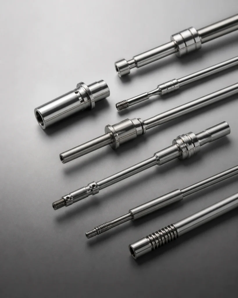
Swiss-Type Precision Machining: How One-Setup Processing Makes Micro Components More Predictable
For small, slender, feature-dense parts, the decisive advantage is not simply a tighter machine tolerance. It is keeping the part, its datums, and its critical features under control from the first cut to the last.
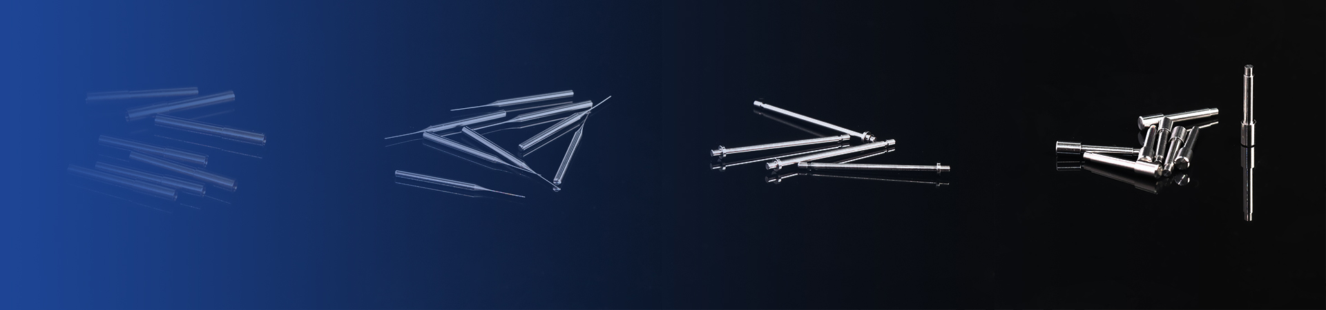
When a shaft, pin, needle component, contact, or miniature actuator part moves from a conventional turning route to a Swiss-type CNC machine, the change is more fundamental than a different lathe layout. A sliding-headstock platform supports the stock close to the cutting zone and can coordinate turning, cross drilling, milling, threading, grooving, cut-off, and back working in a continuous sequence. For the right family of parts, this turns a chain of loosely connected operations into one controlled datum strategy.
This article explains the engineering logic behind Swiss-type precision machining, often marketed as “one-pass” or “one-setup” machining. It is written for mechanical engineers who need to decide whether a micro component should be routed to Swiss CNC, what to show on the drawing, and which claims deserve a process review rather than a marketing assumption.
Engineering answer in one paragraph
Swiss-type CNC machining is most effective for small-diameter, long, or feature-rich rotational parts. The bar moves through a guide bushing while the tool works very near its support point. With live tools and a sub-spindle, many features can be finished without re-clamping the part on a second machine. The resulting benefit is primarily better control of feature-to-feature relationships, then reduced handling and cycle time. It does not remove the need for realistic tolerances, burr control, inspection planning, or qualification.
What “Swiss-Level One-Setup” Actually Means
“Swiss-level” is useful shorthand, but it is not a universal technical standard. In a sourcing discussion, translate it into a machine configuration and a process commitment. The relevant machine is a Swiss-type or sliding-headstock CNC lathe. Rather than holding a fixed workpiece in a chuck with the cutting zone some distance away, it feeds bar stock through a guide bushing. The support is close to the cut, so a slender workpiece has less unsupported length available to deflect.
“One setup” does not mean one tool touches the part once. It means the manufacturing sequence is designed so that the main-spindle work, live-tool features, transfer to the sub-spindle, and back-side work are completed under one coordinated machine setup. A component can still receive washing, deburring, passivation, polishing, heat treatment, or specialized finishing later. The important distinction is that primary geometry is not repeatedly re-established on unrelated fixtures.
This approach matters most where position, concentricity, runout, flat-to-hole relationships, or burr condition are more difficult to recover after a re-clamp than the individual dimensions are to cut. It also matters when production quantity makes manual handling a consistency risk.
Why Micro Precision Machining Changes the Problem
At ordinary sizes, a process may absorb a small amount of deflection, thermal drift, or tool wear without changing function. At micro scale, those same effects compete directly with the feature being made. A tiny drill does not have much torsional reserve. A narrow groove gives chips few places to go. A burr that seems visually insignificant may prevent assembly, alter a fluid path, or damage a mating component.
That is why micro precision machining is not simply conventional CNC machining with smaller tools. The process window becomes narrower: stock straightness, collet condition, guide-bushing clearance, spindle runout, cutting-fluid delivery, chip evacuation, tool wear, and measurement method all influence the result. A credible manufacturing review connects these variables to the drawing's critical-to-function requirements.
| Engineering concern | Why it grows at micro scale | Useful drawing or RFQ input |
|---|---|---|
| Feature location | Datum changes can consume a large part of the allowed position tolerance. | Identify functional datums and the features that must relate to them. |
| Tool access | Small tools have limited reach and are sensitive to runout and chip packing. | Section views, blind-hole depths, corner conditions, and allowable tool relief. |
| Burr condition | A microscopic burr can affect fit, flow, electrical contact, or patient-facing surfaces. | State the allowable edge condition; avoid “deburr” as the only requirement. |
| Inspection | Contact probes may distort thin features and sample size must reflect risk. | List CTQs, measurement method preferences, and record requirements. |
The Real Payoff: Better Feature Relationships
It is tempting to describe Swiss machining as “more accurate.” The better question is: accurate relative to what? A pin diameter can be correct after several operations and still fail because a transverse hole is shifted relative to a shoulder, a milled flat is clocked incorrectly, or a back-side thread is no longer concentric with the front-side pilot.
Each re-fixture introduces a new locating event. The error is not automatically large, but its direction and contribution must be managed. In a one-setup Swiss route, the process can build the feature family from a more consistent reference. The sub-spindle captures the part before separation, enabling backside work without the loose-part handling that would otherwise break that continuity.
Representative Case: A Micro Pin with Front- and Back-Side Features
A small stainless-steel pin was specified with stepped diameters, a shoulder, a cross-hole, a milled flat, and a back-side retention feature.
Conventional risk
Turning the front profile, moving the part to a drill fixture, then re-clamping for the rear feature can make cumulative location error and handling damage difficult to separate during troubleshooting.
Swiss-type route
Front diameters and shoulder are turned from supported bar stock; the cross-hole and flat are live-tooled; the sub-spindle receives the part for rear work before controlled cut-off.
In the Swiss route, the shop can use the turned shoulder as part of a continuous internal process reference rather than trying to rediscover it in a later fixture. This is not a guarantee that every tolerance will be achieved. It does, however, remove an avoidable source of variation and makes capability studies easier to interpret.
The engineering handoff should include material condition, diameter tolerances, surface-finish callouts, the relationship of the cross-hole to the functional shoulder, any no-burr zones, and the inspection report needed for launch. If the part is medical, aerospace, or safety-related, traceability and validation requirements must be settled before the route is frozen.
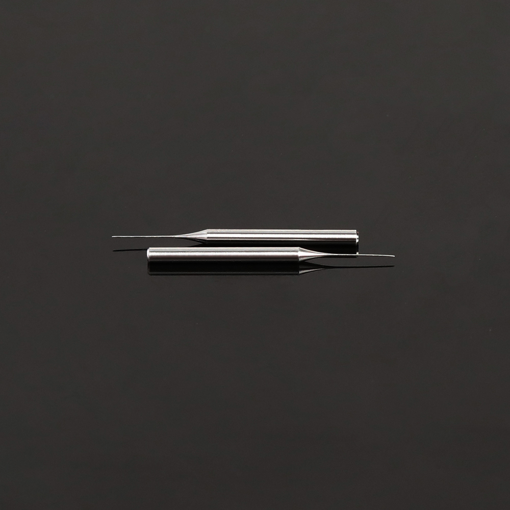
DFM Guidelines for Swiss CNC Micro Components
1. Start from function, not a blanket tolerance
Specify the dimensions that control fit, sealing, motion, electrical performance, or strength. An unnecessarily tight tolerance on every non-critical feature can drive inspection cost and restrict the process without improving the assembly. A short note identifying CTQs often helps a machinist build a more robust route than a drawing full of identical limits.
2. Make the datum scheme executable
When a flat, hole, slot, or thread is functionally related to a shoulder or pilot, show the relationship explicitly. Do not rely on a chain of dimensions taken from unrelated ends of the part. For micro features, datum strategy is often more valuable than adding another decimal place.
3. Give small tools somewhere to go
Blind holes, narrow slots, and deep bores require a chip and coolant strategy. Avoid sharp internal corners when a radius is acceptable; provide tool runout relief where a shoulder needs to be truly functional; and distinguish a cosmetic recess from a feature whose floor geometry matters. The manufacturability check should include tool diameter, reach, material, and removal volume together.
4. Treat material as a process input
Free-machining brass, stainless steel, titanium, copper alloys, and engineered polymers do not cut alike at small scale. Material grade, temper, incoming straightness, and surface condition influence bushing behavior, chip form, tool wear, and final finish. Name the material standard and approved alternates rather than describing only a generic alloy family.
5. Define edge condition where it matters
“Break sharp edges” is not enough for many micro parts. Identify insertion edges, fluid paths, optical or sensing zones, and mating surfaces. The manufacturing team can then choose an appropriate controlled process—toolpath treatment, brushing, micro-abrasive flow, electrochemical finishing, or another approved method—rather than applying a generic deburr operation.
Quality Planning: Make Measurement Part of the Route
Micro parts can be fast to make and slow to prove. An effective plan defines the measurement method at the same time as the cutting process. Optical systems are useful for small holes, profiles, edges, and tiny radii; contact measurement may be appropriate for a robust external diameter but inappropriate for a delicate wall. Surface measurement, visual inspection, gauges, and lot sampling should all be linked to the actual failure mode.
Xproto can plan process monitoring, optical inspection, and traceable quality records around the exact program requirements. As with any supplier claim, a released program should confirm achievable limits for the geometry, material, volume, surface requirement, inspection method, and acceptance criteria. The drawing, not a headline capability, remains the contract.
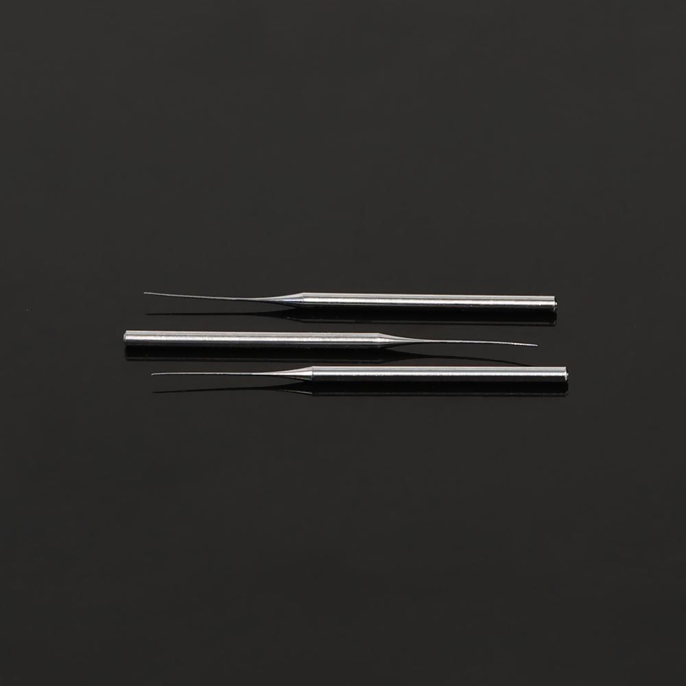
When Swiss-Type Machining Is—and Is Not—the Right Choice
Swiss CNC is a strong candidate when the part is relatively small in diameter, long or slender, rotational at its core, and has several secondary features that benefit from continuous processing. Typical applications include miniature shafts, pins, contact components, connector elements, instrument parts, surgical-device elements, valve components, and precision fasteners.
It is not automatically the best answer for every small part. A short, large-diameter component may be more economical on a conventional turning center. A prismatic part with extensive pocketing may belong on a machining center. Extremely thin or unusual geometry may need EDM, grinding, laser processing, molding, or a hybrid route. The routing decision should compare the entire process: setup count, material yield, tooling, inspection, secondary processing, risk, and expected volume.
What to Send with a Swiss Machining RFQ
- 2D drawing with GD&T, functional datums, material specification, revision level, and finish callouts.
- 3D model when it clarifies non-rotational features, but never as a substitute for the released drawing.
- Annual and release quantities, prototype expectation, and required lead time.
- CTQ list: features that affect fit, motion, leakage, electrical performance, safety, or downstream assembly.
- Acceptance plan: first-article report, material certificates, sampling level, special measurement records, packaging, and traceability needs.
- Known process constraints, including approved finishing routes or restrictions on lubricants, chemistry, and handling.
Turn a micro-part drawing into a manufacturable process plan.
For a useful Swiss CNC review, start with the feature relationships, material, volume, and inspection requirements—not only the tightest dimension on the print.
Discuss Your Part with XprotoHäufig gestellte Fragen
What is the difference between Swiss-type CNC machining and conventional CNC turning?
A Swiss-type machine feeds stock through a guide bushing near the cutting zone, while a conventional lathe usually holds a more stationary workpiece in a chuck. The Swiss arrangement is especially useful for small, slender parts and for integrating several operations in one controlled sequence.
Does one-setup machining eliminate every secondary operation?
No. It can integrate many primary machining operations, including back-side work, but cleaning, specialized deburring, heat treatment, coatings, polishing, and validation may still be required. The value is fewer primary re-clamps and a more continuous datum chain.
Can a Swiss machine make a true micro feature?
It can be a good platform for micro features, but feasibility is feature-specific. Tool diameter, depth, material, burr risk, cooling, chip removal, and how the feature will be measured must all be reviewed before a capability commitment is made.
What is the most useful way to request a tight tolerance?
Identify the functional datum and state the required geometric relationship, not only a decimal limit. Pair that with the intended measurement method and the feature's role in the assembly.