

CNC Machining · Engineering Guide
Swiss-Type Precision Machining: A Practical Guide to One-Setup Micro Parts
Guide-bushing support, sliding-head motion, live tooling, and a sub-spindle can turn a long, delicate bar into a finished component without repeatedly changing its datum.
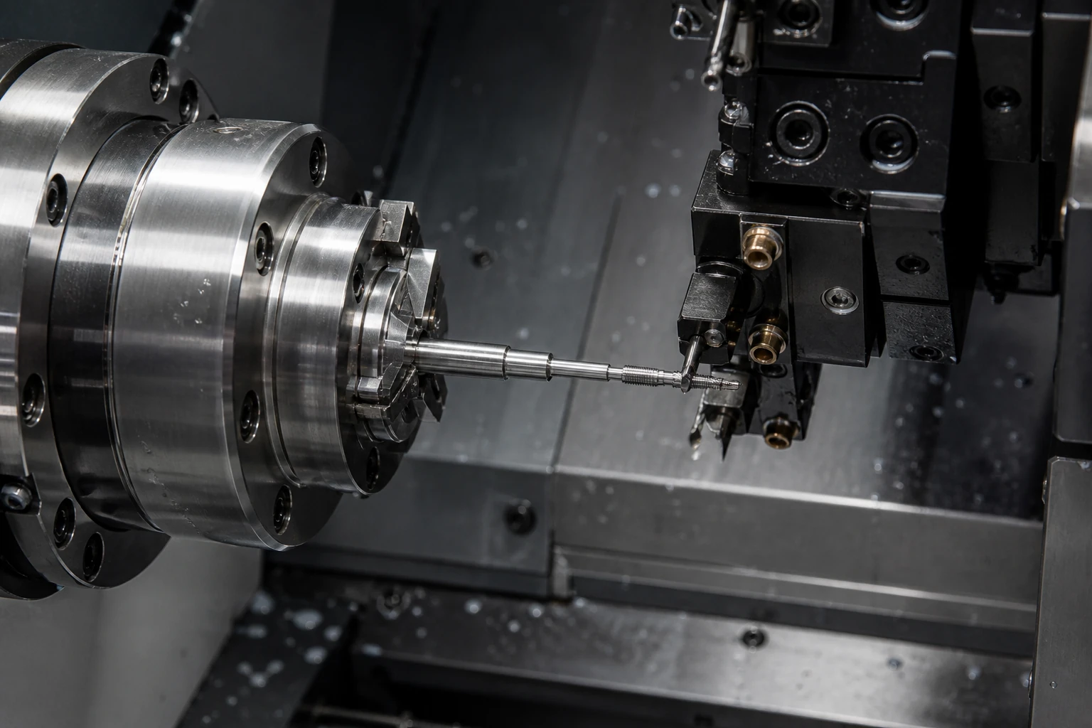
A slender shaft can look simple on a drawing and still be awkward to manufacture. Once the cutting force reaches a small unsupported diameter, the bar may bend, chatter, or spring away from the tool. Add cross holes, flats, threads, and tight positional requirements, and a conventional sequence may require several setups. Each transfer adds time and another opportunity for datum error.
Swiss-Type Precision Machining addresses that problem by changing how the material is supported and moved. Instead of exposing a long section of bar, a sliding headstock feeds stock through a guide bushing so cutting happens close to the support point. On a modern machine, turning tools, live tools, and a sub-spindle can work in a coordinated cycle. The result is not automatically a perfect part, but it gives process engineers a strong platform for controlling small, slender, feature-dense components.
Swiss machining is most valuable when part geometry creates a support problem or when one-setup production removes several risky handoffs. It should be selected from the geometry and production plan—not simply because the diameter is small.
What Is Swiss-Type Precision Machining?
A Swiss-type lathe is a CNC turning platform with a sliding headstock. Bar stock passes through a guide bushing, and the headstock moves the material along the Z-axis while tools cut near the bushing face. This is the defining difference from a conventional fixed-head lathe, where the workpiece is clamped in a stationary headstock and tools generally travel along the part.
The layout grew from the need to make small watch components, but today it is used for medical pins, electronic contacts, fluid fittings, miniature fasteners, valve parts, and narrow aerospace or automation components. Modern machines may include live milling, drilling, polygon cutting, thread whirling, and back-working. That combination makes “turning” an incomplete description; many parts leave the machine with both round and milled features complete.
How the Sliding Head and Guide Bushing Control the Cut
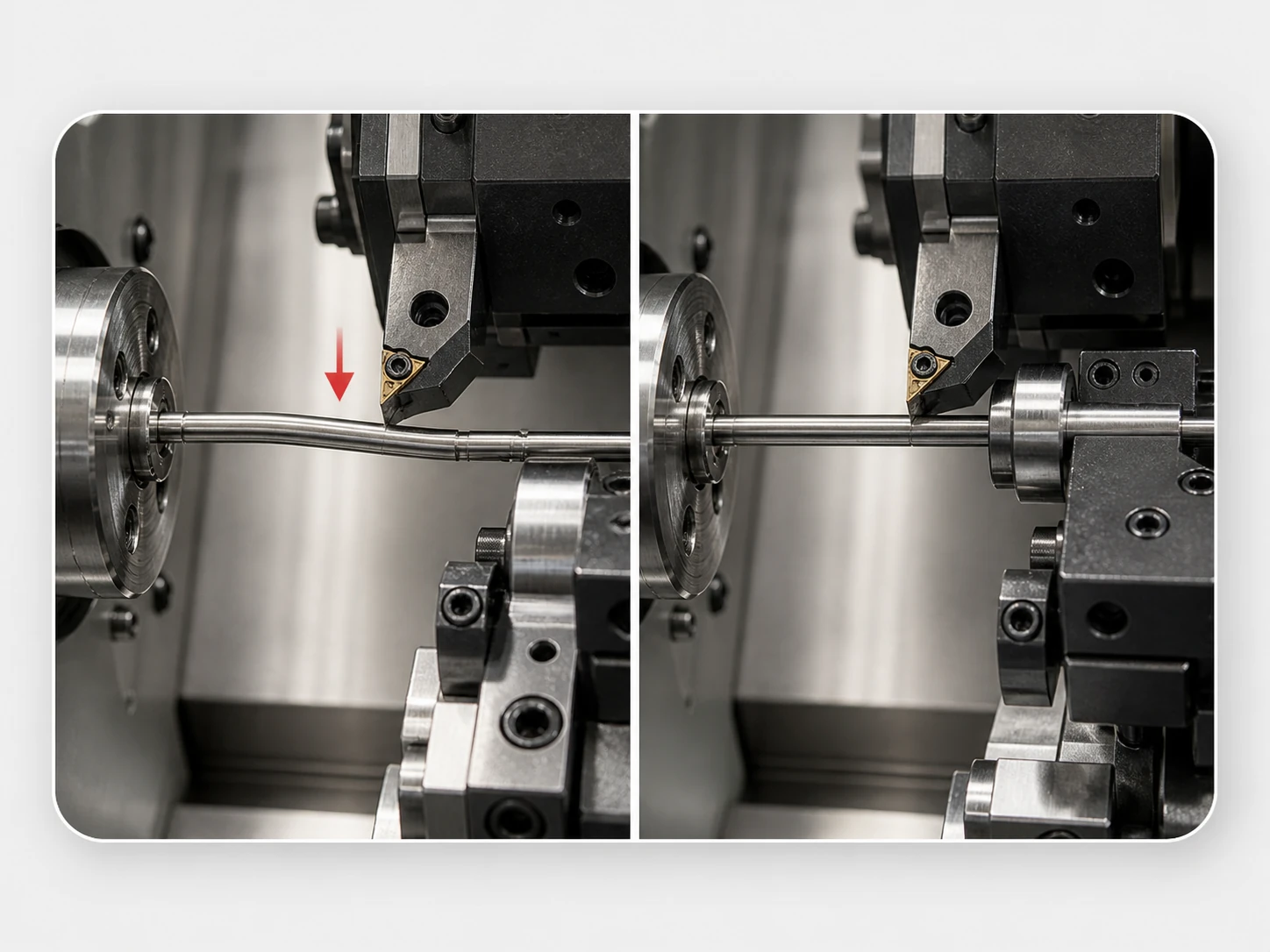
The guide bushing supports the bar immediately behind the active feature. Because the unsupported length is short, the stock has less room to deflect under cutting pressure. This matters because bending sensitivity rises quickly as a slender section becomes longer. Keeping the tool close to the support can therefore improve diameter control, roundness, surface finish, and stability.
Support is only part of the story. The bar must also suit the guide bushing. Poor straightness, inconsistent bar diameter, or damaged stock can produce friction and size variation. The bushing clearance, tool geometry, cutting parameters, coolant delivery, and chip evacuation must be treated as one system. A capable machine cannot compensate for a weak process plan.
Why One-Setup Processing Changes the Result
Part handling is often an invisible source of variation. A turned blank made on one machine, moved to a mill, and then returned for secondary work must be located again each time. Concentricity and true-position requirements may now depend on several fixtures, operators, and datum transfers.
With Swiss-Type Precision Machining, live tools can drill radial holes, mill wrench flats, engrave marks, or cut slots while the main spindle still controls the part. A sub-spindle can grip the nearly finished component before cut-off, then present the back end for facing, drilling, or threading. When the geometry and machine configuration align, the cycle establishes a more continuous datum chain and sends a nearly complete part to inspection.
| Decision factor | Swiss-type CNC | Conventional CNC lathe |
|---|---|---|
| Work support | Guide bushing close to the cutting zone | Work projects from a chuck or collet |
| Strongest geometry | Small-diameter, long, slender, feature-dense parts | Shorter, larger-diameter, less slender parts |
| Secondary features | Often integrated with live tooling and a sub-spindle | Available on many machines, but configuration varies |
| Setup economics | More planning, with strong repeat-production potential | Often simpler for low quantities and basic geometry |
Which Parts Benefit Most?
The best candidates usually combine a small diameter with one or more process challenges. Look for a high length-to-diameter ratio, thin walls, multiple diameters, cross holes, slots, flats, threads, or important relationships between front and back features. Parts that arrive in steady quantities also benefit because automated bar feeding spreads setup effort across more pieces.
Common materials include stainless steel, carbon and alloy steel, aluminum, brass, copper, titanium, and selected engineering plastics. Machinability still affects cycle time and tool life. Free-machining brass behaves differently from gummy stainless steel; titanium demands careful heat and tool-wear control. Material certification, corrosion requirements, magnetic properties, biocompatibility, and finishing needs should be identified before quoting.
Tolerances: What Is Realistic?
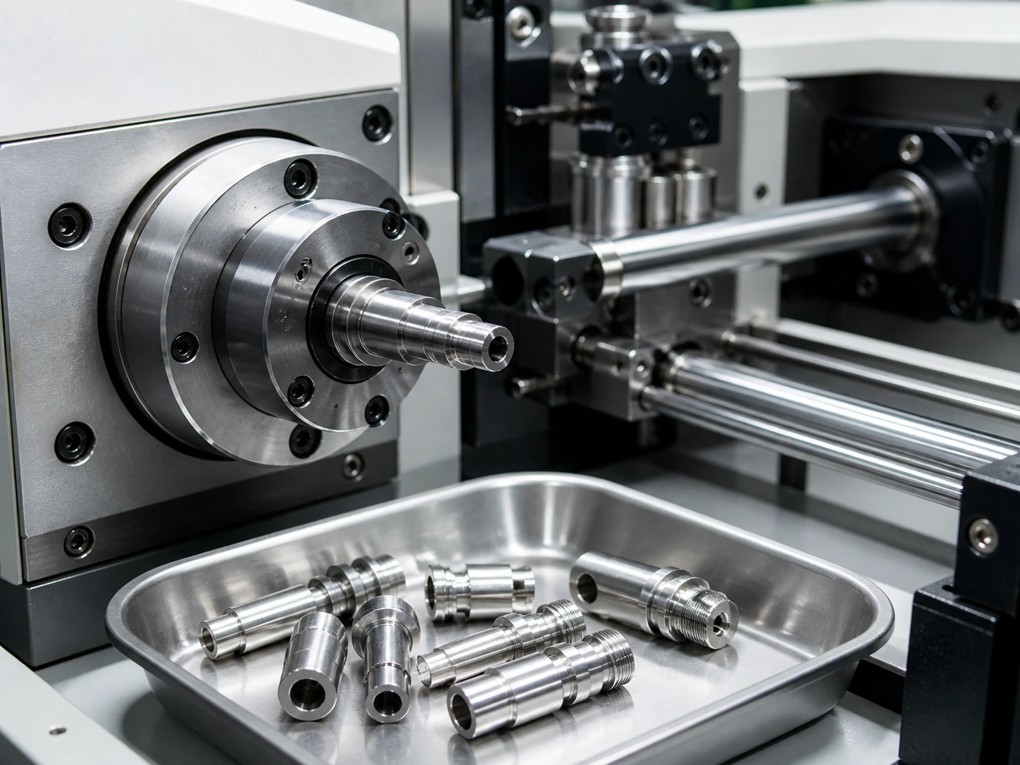
There is no universal tolerance that every Swiss-machined feature can hold. Capability depends on size, geometry, material, tool reach, thermal stability, measurement method, and batch length. For suitable features, ±0.01 mm may be practical; a critical feature near ±0.005 mm may also be reviewed, but it should never be presented as a blanket promise for an entire drawing.
Use tighter tolerances where function requires them and general tolerances elsewhere. Also define what matters: diameter alone does not control straightness, cylindricity, concentricity, or the position of a cross hole. A good request for quotation identifies critical-to-function features, datum relationships, surface-finish requirements, thread standards, inspection level, and acceptance criteria. That information allows the manufacturer to plan tooling and metrology around the actual risk.
A Practical DFM Checklist
- Provide a clean 3D model and a controlled drawing. Mark critical dimensions rather than tightening every value.
- Review stock size and bar quality. Guide-bushing performance depends on consistent material diameter and straightness.
- Reduce deep, narrow features where possible. Fragile tools, poor chip clearance, and long reach increase risk.
- Standardize threads and radii. Common tools shorten setup and simplify replacement during a production run.
- Plan burr-sensitive intersections. Cross holes and slots may need a defined edge condition or a secondary deburring method.
- Discuss annual quantity, not only the first order. The right decision may change when setup cost is spread over repeat batches.
A feature-dense connector pin
Consider a 3 mm stainless-steel connector pin with two stepped diameters, a narrow groove, an axial bore, a cross hole, and a finished back face. A conventional route might turn the blank, transfer it to a milling fixture, and re-chuck it for back work. A Swiss process can turn and groove near the guide bushing, drill the cross hole with live tooling, hand the part to the sub-spindle, cut it off, and finish the rear face. The practical gain is not a dramatic tolerance claim. It is fewer datum transfers, less work-in-process, and a clearer path to repeatable inspection.
When Swiss Machining Is Not the Best Choice
A process should earn its place. A short, thick component with simple turning and a very small order may be faster and less expensive on a conventional CNC lathe. A part dominated by broad prismatic surfaces may belong on a machining center. Very short prototype runs can also make Swiss setup and tooling disproportionate to the quantity.
The useful question is not “Can this fit on a Swiss machine?” It is “Which route controls the critical features with the fewest unstable operations at the required volume?” A manufacturer should be willing to recommend a simpler method when it serves the drawing better.
Frequently Asked Questions
What is the main advantage of Swiss-Type Precision Machining?
Its main advantage is stable support close to the cutting zone. Combined with live tooling and a sub-spindle, this can reduce deflection and complete several features without repeated re-clamping.
Is Swiss CNC machining only for long parts?
No. Long, slender parts are strong candidates, but short parts with many turned and milled features can also benefit from one-setup processing and automated bar feeding.
What diameter can a Swiss-type machine handle?
Capacity varies by machine and bar-feeding system. Send the maximum stock diameter, finished geometry, and quantity to the manufacturer so the exact machine envelope can be confirmed.
Can a Swiss machine mill flats and drill cross holes?
Yes, when the machine has the required live-tool stations and axis configuration. Tool access, feature depth, and burr control still need a DFM review.
What files should I send for a Swiss machining quote?
Send a STEP model and a PDF drawing that identifies material, critical tolerances, datums, threads, surface finish, finishing, inspection requirements, and expected quantities.
Ready to Review Your Small Precision Part?
Share your model, drawing, material, and quantity with Xproto. Our team can review whether Swiss-type turning, conventional CNC turning, or another manufacturing route is the better fit.