

CNC Machining Engineering Guide
Surface Roughness Chart: Ra, Rz, RMS and CNC Finish Guide
A surface finish callout can look like a small note on a drawing, yet it can change the cutting strategy, inspection method, lead time, and price of a CNC machined part. This guide explains what the common numbers mean and how to specify the finish your part actually needs.
What Does Surface Roughness Actually Measure?
No machined surface is perfectly flat. Under magnification, it contains peaks, valleys, feed marks, and small irregularities left by the tool and material. Surface roughness describes the closely spaced texture of that profile. It is different from waviness, which covers broader undulations, and from form error, such as taper, bow, or out-of-roundness.
This distinction matters because a part can meet dimensional tolerance and still fail in service. A seal may leak across deep tool marks. A sliding shaft may wear quickly if high peaks carry the load. A painted surface can show machining lines even when its size is correct. Roughness is therefore a functional requirement, not simply a cosmetic grade.
Measurements are normally reported in micrometres (µm) or microinches (µin). The instrument, filter, cut-off, sampling length, measurement direction, and evaluation rule all influence the reported result. When the function is important, a bare number such as “Ra 0.8” is better than “smooth,” but it may still need a stated standard and measurement direction.

Ra vs. Rz vs. RMS: The Practical Difference
Ra: arithmetic average roughness
Ra is the arithmetic mean of the absolute profile-height deviations from the mean line over the evaluation length. It compresses a large amount of profile data into one stable, familiar number. That makes it useful for general drawing control, supplier communication, and process comparison.
Its limitation is equally important: very different profiles can have the same Ra. A surface with many small, regular marks and one with a few sharp valleys may produce a similar average. When isolated defects or sealing performance matter, Ra alone may not describe enough.
Rq or RMS: root mean square roughness
Rq is the root mean square of the profile deviations and is commonly called RMS roughness. Squaring the deviations before averaging gives greater influence to larger peaks and valleys. Rq is therefore normally a little higher than Ra for the same profile.
You may see the shortcut Rq ≈ 1.11 × Ra, or Ra ≈ 0.90 × Rq. It can be a reasonable estimate for certain regular or near-Gaussian profiles, but it is not a universal conversion. The actual relationship depends on the surface-height distribution. Do not use the approximation to accept or reject a production part.
Rz: peak-to-valley sensitivity
Rz responds more strongly to profile extremes than Ra, which makes it useful for detecting pronounced tool marks, scratches, or valleys that could affect sealing and wear. The catch is that “Rz” has not meant exactly the same thing in every historical ISO, DIN, JIS, or ASME context. Modern ISO 21920 defines the parameter within its current profile framework, while older drawings and instruments may follow earlier conventions.
If a drawing specifies Rz, state the applicable standard or confirm it with the customer. Converting Rz to Ra using a fixed multiplier can hide the very peaks and valleys that Rz was chosen to control.
Use Ra when
You need a widely understood overall finish value for normal machining, purchasing, and inspection.
Add Rz or profile data when
Sealing, lubrication, wear, coating, fatigue, or isolated surface damage makes extremes important.
Surface Roughness Chart: Ra, Microinch and N Grades
The chart below converts common Ra values between micrometres and microinches and shows the traditional N-grade reference. The process descriptions are planning guidance, not guaranteed capability. Real results depend on the machine, tool, material, geometry, access, and measurement method.
| N grade | Ra (µm) | Ra (µin) | General interpretation | Possible process route |
|---|---|---|---|---|
| N12 | 50 | 2000 | Very coarse | Rough cutting or heavy stock removal |
| N11 | 25 | 1000 | Coarse | Rough machining |
| N10 | 12.5 | 500 | Visible heavy tool marks | Rough turning or milling |
| N9 | 6.3 | 250 | Normal rough-machined finish | General machining before finishing |
| N8 | 3.2 | 125 | Common commercial machined finish | Controlled CNC milling or turning |
| N7 | 1.6 | 63 | Fine machined finish | Finish milling or finish turning |
| N6 | 0.8 | 32 | Very fine machined finish | Careful finish cutting or grinding |
| N5 | 0.4 | 16 | Precision smooth finish | Fine grinding, honing, or polishing |
| N4 | 0.2 | 8 | High-grade precision surface | Precision grinding, honing, or lapping |
| N3 | 0.10 | 4 | Very high-grade surface | Fine lapping or superfinishing |
| N2 | 0.05 | 2 | Ultra-fine | Specialized lapping or polishing |
| N1 | 0.025 | 1 | Exceptional finish | Specialized superfinishing |
What Surface Finish Can CNC Machining Produce?
For many custom parts, Ra 3.2 µm is a practical as-machined requirement. A finer Ra 1.6 µm surface is also common on functional faces when the geometry and tool access support a finishing pass. Ra 0.8 µm may be achievable by controlled turning or milling on suitable features, but it demands more attention to setup rigidity, tool edge, material behavior, and inspection. Below that level, grinding, honing, lapping, or polishing often becomes the more predictable route.
Those values should never be treated as universal machine limits. A broad, accessible turned diameter behaves differently from the floor of a deep milled pocket. Thin walls can chatter. Long, slender parts can deflect. Interrupted cuts, difficult alloys, small internal radii, and inaccessible faces may require a different process plan.
Factors that change the result
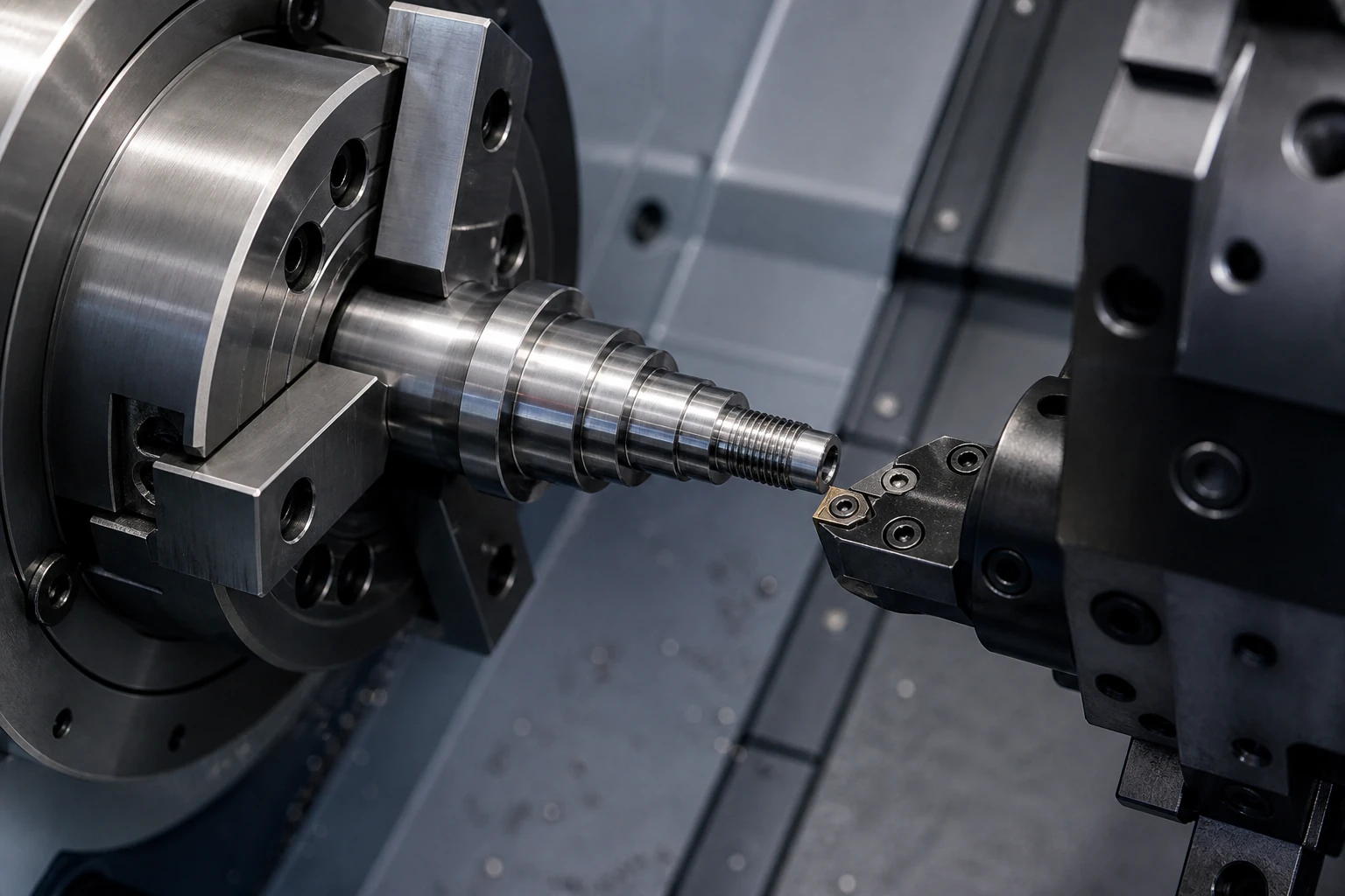
- Feed and tool geometry: feed marks and nose radius strongly influence the theoretical profile.
- Tool wear and built-up edge: a tool can hold size while leaving a poor surface.
- Rigidity: chatter from the machine, fixture, tool, or workpiece creates periodic marks.
- Material: gummy aluminum, stainless steel, hardened steel, and engineering plastics cut differently.
- Coolant and chip control: recutting chips can scratch an otherwise acceptable finish.
- Measurement direction: measuring across the lay often gives a different result from measuring along it.
How to Specify Surface Roughness Without Overpaying
The safest drawing begins with function. Ask what the surface must do: seal, slide, retain lubricant, accept paint, locate another component, or simply look clean. Then apply the requirement only to the affected faces. A blanket Ra 0.8 µm note can add finishing and inspection work to every pocket and wall even when most of them do not need it.
State the parameter, numerical limit, and units—for example, Ra 1.6 µm max. For critical applications, also state the governing standard, measurement direction, cut-off or filtering requirement, evaluation length, and acceptance rule. If Rz is used, identifying the standard is especially important. A drawing note should be measurable by both supplier and customer in the same way.
A finish requirement also needs space in the process plan. Finishing can remove material, soften edges, change dimensions, or alter coating thickness. Coordinate roughness with dimensional tolerance, edge-break notes, heat treatment, plating, and final inspection. The best result is not the smallest Ra number; it is the least costly controlled surface that reliably performs its job.
A useful RFQ checklist
- Mark only the faces that require a controlled finish.
- Specify Ra, Rz, Rq/RMS, or another parameter intentionally.
- Write the units and whether the value is a maximum or a range.
- Identify the applicable ISO, ASME, DIN, or customer standard.
- Include the measurement direction when the machining lay matters.
- Separate cosmetic expectations from measurable roughness limits.
- Share mating, sealing, wear, coating, and lubrication requirements with the supplier.
Surface Roughness FAQ
What is the difference between Ra and Rz?
Ra averages the absolute profile deviations and is useful for general finish control. Rz places more emphasis on peak-to-valley behavior and can reveal extremes that Ra may hide. Because Rz definitions vary by standard and era, the drawing should identify the standard used.
Is RMS the same as Rq?
In surface-roughness discussions, RMS usually refers to Rq, the root mean square height of the roughness profile. Rq weights larger deviations more heavily and is normally higher than Ra for the same measured profile.
Can Ra be converted directly to Rz?
Not reliably. Published ratios are only estimates because two surfaces with the same Ra can have very different peak and valley structures. Production acceptance should use the specified parameter measured directly under the stated standard.
What is a common CNC machined surface finish?
Ra 3.2 µm is a common practical as-machined value, while Ra 1.6 µm is often requested for finer functional surfaces. Actual capability depends on material, geometry, tool access, rigidity, and the selected process.
Does a lower Ra always make a better part?
No. An unnecessarily low Ra can increase cycle time, finishing operations, inspection, and price without improving function. Some lubricated surfaces also benefit from controlled texture rather than a mirror-like finish.